The determination of the thermal conductivity of building materials is fundamental for solving problems related to building performance and user comfort. A variety of organic insulation products have been recently promoted for their sustainability, which includes crop-based materials [1, 2]. Among these some require a great thickness of implementation, either because their very nature requires it, like for straw bales construction [3-5], or to compensate for their lower thermal conductivity relatively to high performance inorganic insulation materials. There are many methods for measuring the thermal conductivity of materials, both in steady state and transient conditions. The stationary methods such as the so-called 'guarded hot plate technique' require thermal equilibrium and thus a significant measurement time. The boundary conditions imposed on the sample need also to be controlled precisely. However, if these boundary conditions are met, the results obtained by these methods are often very accurate [6]. The transient methods provide generally faster results and can be used on smaller samples but at the cost of lower accuracy.
The work presented here was directed towards the conception of an apparatus for thermal conductivity measurement in steady state, capable of performing over a wide range of thickness.
More specifically it's expected to provide reliable results on an entire straw bale. This would be particularly useful to assess the effect of actual straws particles orientation in the bale on final thermal conductivity. This information might be particularly relevant for producers targeting the construction sector.
Much research has already been conducted on the thermal conductivity of straw bales. The effect of the direction of heat flow relatively to fibers orientation has already been highlighted [7-9]. It is accepted that the more the flow is parallel to the fibers, the greater the thermal conductivity. It is important to note however that most of available data drives either from transient methods [10], from steady-state methods performed on lower thickness re-built bales [11] or from compressed loose material [12, 13]. Absolute thermal conductivity measurements on an entire two-wired straw bale are thus still missing. The rearrangement of the samples often observed in literature for steady-state measurement is required by the low thickness generally imposed by commercial guarded-hot plate or heat flow meter apparatus. As the straw particle length can generally extend to 50cm [14], resetting lower thickness samples from original bale could lead to changes in structure the impact of which is hard to quantify.
The guarded hot plate prototype presented here allows measurements on thick specimens and offers the possibility to assess the thermal conductivity of non-altered straw bales samples. The approach is thus complementary to existing data. It offers the possibility of direct and easy comparison of bales from different origins or manufacturing. The original device is described in this paper along with particular design details and challenges encountered. Its performance will be assessed by performing the necessary numerical and experimental tests.
GUARDED HOT PLATE METHOD
2.1 General principle
The guarded hot plate (GHP) apparatus is traditionally recognized as the only absolute method for thermal conductivity measurement in steady-state of homogeneous materials able to achieve a global measurement uncertainty below 2% [6]. Its principle is to reproduce the uniform,
unidirectional and constant thermal flux density existing through an infinite homogeneous slabshaped specimen caught between two infinite isothermal planes. The method is defined in an international standard under the designation 'Thermal insulation - Determination of steady-state thermal resistance and related properties - Guarded hot plate apparatus' [15].
The device developed in this research is based on the 'single specimen apparatus' (Fig. 1). Their principle is the following: the analyzed specimen is sandwiched between an electrically-heated hot plate maintained at temperature ??? and a cold plate maintained at a lower temperature .The heat dissipated by the Joule effect in the hot plate would travel to the cold plate through the sample, but also backwards and laterally on the edges of the hot plate. Back and lateral 'guard zones' are then necessary to neutralize these leaks. By maintaining the different guard zones at the same temperature ??? with precise control, all unwanted thermal transfers are indeed canceled. The hot plate is thus separated in two parts: a heater zone (or measurement zone) of known area and heated electrically and an adjacent guard ring heated with a different circuit. A small gap separates the two zones and a thermopile is often used to control the temperature difference between these. The back face of the hot plate is provided with an additional guard plate with identical dimensions providing protection from backwards thermal fluxes. This back guard plate also has its own heating system and is associated with appropriate temperature differential control as in lateral gap.
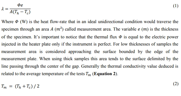
When working well, with all three elements at exactly the same temperature, the heat produced in the measurement plate will flow unidirectionally towards the cold plate. All the others heat fluxes are supposed to be eliminated. With such device, the thermal conductivity is obtained by the one-dimensional Fourier equation:
Chosen measurement approach
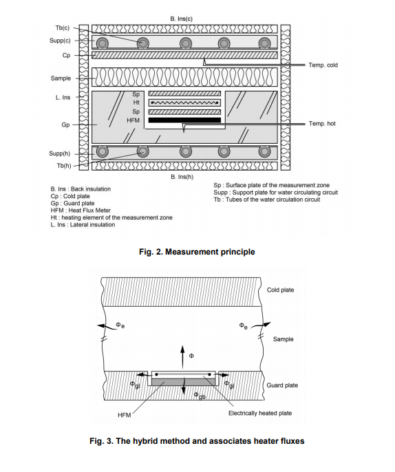
Figure 2 shows the schematic diagram of the GHP prototype presented here and highlights the differences in measurement strategy in comparison to a typical single specimen apparatus (Fig.1). We will used what is referred as a 'hybrid method' [16] to obtain the heat flux ?? crossing the specimen, similarly to the device developed in [17]. The lateral and back guard plates are combined into a single massive metallic piece, called simply the guard (or hot) plate, and circulating water passing through tubes and thermal diffusers is used to maintain it at the temperature ???. The measurement plate is incorporated in the center of this guard plate and electrically-heated. A heat flux meter (HFM) is sandwiched between the unique guard plate and the heater and allows to control precisely the temperature difference between the two pieces.
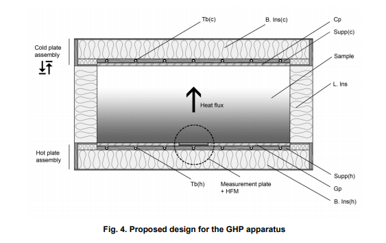
Figure 3 presents more precisely the principle of the hybrid method with the different heat fluxes involved. At steady state the heat balance on the heater plate gives:
Where is the electric power dissipated in the electric resistive circuit,is the heat flux actually passing through the sample,the heat flow passing to the guard plate laterally through the gap, the back heat flux going to the guard plate through the HFM and he edge loss, i.e. the heat produced by the heater that derives from the ideal vertical flow orientation and leave the sample through its edges. All these 'leak' fluxes depend on the temperature difference between the guard plate and the heater plate as well as the temperature of the edge of the sample during the test. When the temperature is the same in the guard and measurement plate and the edge of the sample is well insulated or far enough from the heater plate, it can be assumed that all the electrical power dissipated in the heater flows vertically through the sample, In appropriate designs is typically less than 0.5% of ?? [15].
OVERVIEW OF THE GHP APPARATUS
3.1 General specifications
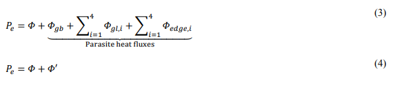
The conception of the GHP presented in this research was made in accordance with ISO 8302 recommendations [15], in order to guarantee an accuracy of 2% for mean test temperature around the ambient temperature and a repeatability of 0.5% with two successive measurements on the same sample. The proposed final design for the apparatus is shown on Figure 4 which gives a general section view. The slab square-shaped specimen with thickness ?? is placed between a hot plate assembly and an upper cold plate assembly, mounted horizontally on a support frame. A rail system allows to displace the cold plate assembly vertically, to adjust the GHP to the thickness of the sample. On its lateral faces, the sample is surrounded by lateral (or edge) insulation.
Table 1 shows the general performance specifications of the GHP apparatus, presented
similarly to [18]. The GHP device was designed to measure thermal conductivity on building construction materials with thermal resistance ranging from 0.1 to 151. In practice,the principal limitation is the maximum power that the heater plate is able to give, i.e. 1. For a temperature difference of 10°C between the hot and cold plate, the thermal resistance of the specimen is limited in the lower range to 0.225。
. In parallel, the thermal resistance is limited in the upper range by the noise level of the acquisition system for the heater dissipated power. Small temperature difference between the hot and cold plate induces small power dissipation in the heater plate. The limit is thus fixed as before by the acquisition system. Two circulating baths are controlled independently in temperature to maintain the guard plate and the cold plate respectively at the temperature. The upper limit of temperature difference is fixed by the power capacity of these circuits. It should be noted that most of the tests will be conducted with a temperature difference of 10 or 20°C, as they will be performed on insulation materials.
In order to test materials with thickness up to 400mm with acceptable edge heat loss errors the guard area was extended to 425mm laterally all around the measurement plate. The lower limit of the samples thickness is fixed to ten times the size of the gap, i.e. 20mm
3.2 Cold and hot plates assemblies
The hot plate assembly is based on a square aluminum plate with dimensions 1000x1000x15mm giving the necessary width to limit the edge loss error. Aluminum was chosen for its high thermal conductivity and the alloy (6082 T651) for milling workability. A square recess cut with a side of 154mm and depth of 10mm is made in the center of the aluminum plate to host the measurement plate. The cold plate assembly is almost identical, except that there is no measurement bloc and its thickness is limited to 5mm. In both plates assemblies, water circulating channels are used to maintain the isothermal conditions of plates. Each circulating circuit is connected to an independent thermostatic bath through a low discharge pump. The temperature of the baths is controlled over a temperature range of 5-40°C using ProportionalIntegral (PI) regulation with the temperature of the linked plate as feedback. In fact, the PI controller acts on heating elements immersed in the bath that balance the continuous cooling effect of a compressor chiller. Water circulates then through plastic tubes that show a serpentine shape with 7 crossings spaced by 150mm. Tightly attached to them come linear aluminum thermal diffusers that are in direct contact with the main metal plates. The system composed by the tube and the diffusers is supported by a specific wood particle board. The validity of the system in terms of temperature homogeneity at the surfaces of the plates will be assessed by implementation of several temperature sensors at different locations in the plates.
Temperature measurement
3.3.1 Temperature sensors
In order to obtain the thermal conductivity data of the tested material, it is necessary to measure accurately the temperature at different locations, and most particularly at the surface of the plate on either side of the specimen. Most guarded hot plates use thermocouples at this purpose. Here DS18b20 (Dallas) numeric sensors are used instead. They convert temperature in 12-bit mode which offers a resolution of 0.0625°C. In order to obtain the necessary accuracy, 18 sensors (named T1 to T18) are properly calibrated using a certified thermometer (Testo 950 with sensor 06280016) and a thermally controlled stirred liquid bath (Haake C40 with F8 circulator). The sensors are mounted on an electrical plate and are placed in de-ionized water in the bath together with the tip of the reference thermometer. The digital sensors calibration is done at 7 temperature plateaus, from 10 to 40°C with 5°C steps. For each temperature plateau, the water bath was kept at a constant temperature for at least 15 minutes with a thermal precision of 0.01°C. The sampling rate and duration of the sensors measurement are fixed respectively to 10 seconds and 10 minutes, giving a total of 60 measurements per plateau. It was observed to the standard deviation of these measurements is typically less than the resolution of the sensors, which can be considered in consequence the main precision error of our numeric temperature sensors.
The reference thermometer shows a precision of 0.021°C. Its bias error was given at 3 temperature points by a calibration certificate. Figure 6 shows the bias error regression on the interest zone, which will be used to correct measured data. At each calibration temperature, the true temperature value is given by the average of the reference thermometer readings, corrected by the bias error regression. This true value is then compared to the average of the DS18b20 measurements. Their bias is always less than 0.1°C and properly taken into account in the forms of individual correction formulas based on linear regressions.
Once calibrated, the nine chosen temperature sensors are implemented in the cold and guard plates to monitor the temperature at different locations (Fig. 7). Sensors T5, T6 and T7 are used to determine the hot side temperature whereas sensor T12 gives the cold side temperature. The other sensors are complementary and will give information about the temperature homogeneity of the plates and eventually to detect fault behavior. Their placement was chosen after completing some numerical thermal simulations. To implement the different sensors, holes with 4.8mm diameter were drilled to within 2mm of the front surface of the plates (13mm deep) for all sensors except T6 and T7. For these last two sensors, additional holes were drilled in the center of the plate to 1mm of the surface. Finally, additional recess tracks are made to host the leads of the different sensors, so that they come in close contact to the plates, in order to minimize thermal conduction from ambient temperature.
3.3.2 Temperature stability and homogeneity
In order to test temperature homogeneity and stability of the plates an experimental study was performed. The water circuits of the GHP were turned on with a 5cm polystyrene slab between the two plates and the different sensors were continuously monitored. The cold plate temperature was set to 5°C and the hot plate to 15°C, which will be the most frequent test temperatures. There is first the stabilization phase, where plates slowly approach their respective temperature threshold, followed by the steady-state phase. During the test, the room temperature is kept at 20°C, to simulate non-ideal test conditions.
Table 2 shows the average temperature and its standard deviation for all nine implemented sensors during one hour in steady state conditions. With these test conditions, the stability and homogeneity of the hot plate temperature stays below the recommended 0.2°C [9]. This criterion represents actually 2% of the temperature difference between hot and cold plate. For the cold plate, it seems that the apparatus homogeneity is barely respected, with temperature at the center of the plate (T12) a bit lower than on its side (T11 and T13). It can be explained by the position of the central sensor, which lies just under the water circulating tube. Figure 8 shows the temperatures of T4, T7 and T8 for 10 minutes in steady state conditions as illustration purposes. The numeric nature of the sensors can be clearly seen by the specific jumps of temperature readings.
3.4 Measuring the heat flow-rate through the specimen
3.4.1 Measurement plate
The measurement plate is formed of several layers. The heating part strictly speaking is a printed circuit board with dimensions 150x150mm and 1.6mm thick. It consists of a layer of glass fibers sandwiched between two thin 35?m copper layers. A resistive circuit is etched on both copper sides giving a total electric resistance of 33.63 Ω at 20°C. The linear temperature dependence of the resistance is given by 0.136 · T + 30.908, obtained after measuring the total resistance of the heater at several temperature between 5 and 40°C. This circuit board is in turn sandwiched between two 1mm aluminum platelets to enhance the temperature distribution (Fig. 9). These platelets are electrically insulated from the electric circuit by a thin layer of thermal adhesive.
The heating copper resistor is subjected to a pulse-square signal generated by a micro-controller and width-modulated according to the necessary electrical power. In serial with the heater, a 47 Ω reference resistor calibrated with an accuracy of 0.1% is inserted in the circuit. A high precision voltmeter (± 52 ?V) is used to measure the voltage drop across this reference. Knowing this value, the current passing through the circuit is then easily computed. Finally, the power dissipated in the heater is obtained by combining this electrical current, the electrical resistance of the heater plate adjusted with hot plate temperature and the pulse width-modulated signal information.
3.4.2 Heat Flux Meter
The heat flux meter (HFM) is made by serial assembly of several thermoelectric (TE) modules (Fig. 10 and 11) that are inserted between the guard plate and the heater plate. Such TE modules are acting to like heat pump devices when a DC current passes through them i.e. heat will be moved through the module from one of its face to the other. However they can be used in reverse mode, acting like power generator or heat flow detectors [19]. In the hybrid method of heat flux measurement implemented here, such elements are thus really convenient to use as HFM in an open circuit configuration. They allow controlling the flow of heat that goes from the measurement plate area to the guard zone and vice versa. Any heat exchange between the two elements will automatically create an output voltage. In fact under an open thermoelectrical circuit the relation can be written as follow:
Where ?????? (W) is the heat flux between the measurement plate and the guard plate, through the HFM, ?????? is the thermal conductivity of the thermoelectric module, ?????? (??/??) is the Seebeck coefficient of the thermoelectric assembly and ?? the output voltage. Depending on the sign of the output voltage, the measurement plate is either cooler or hotter than the guard plate. Knowing this, the parasite heat flow can be cancelled by adapting the pulse-width-modulated signal that directs energy supply to the heater plate. In practice, 9 thermoelectric blocs with dimension 50x50x4mm are arranged in a tight square shape, giving the exact same area as the measurement plate and are fixed with thermal adhesive on the surface plate of the latter (Fig. 10). Having the entire back area of the measurement plate covered with the HFM is really important in order to take into account local variations of the temperature on the surface of the recess cut of the guard plate. It’s the only way to ensure that the thermal imbalance is accurately taken into account for heater plate input power adjustment.
Finally, a thin insulation layer of 2.44mm thick is fixed on the free side of the HFM and will come in contact with the guard plate. The role of this layer is to filter the small temperature heterogeneities of the guard plate.