1. Purpose and Scope
1.1 This test method is applicable to any textile fabric, which may or may not have been given a water-resistant or water-repellent finish. It measures the resistance to the penetration of water by impact, and thus can be used to predict the probable rain penetration resistance of fabrics. It is especially suitable for measuring the penetration resistance of garment fabrics. With the instrument, tests may be made at different intensities (see 11.1) of water impact to give a complete overall picture of the penetra tion resistance of a single fabric or a combination of fabrics.
1.2 The results obtained with this test method depend on the water repellency of the fibers and yarns, and on the construction of the fabric.
2. Principle
2.1 A test specimen, backed by a weighed blotter, is sprayed with water for 5 min under controlled conditions. The blotter is then reweighed to determine the amount of water which has leaked through the specimen during the test.
3. Terminology
3.1 water resistance, n.óof fabric, the characteristic to resist wetting and penetration by water. (See also water repellency.)
4. Safety Precautions
NOTE: These safety precautions are for information purposes only. The precautions are ancillary to the testing procedures and are not intended to be all inclusive.
It is the userís responsibility to use safe and proper techniques in handling materials in this test method. Manufacturers MUST be consulted for specific details such as material safety data sheets and other manufacturerís recommendations. All OSHA standards and rules must also be consulted and followed.
4.1 Good laboratory practices should be followed. Wear safety glasses in all laboratory areas.
5. Apparatus and Materials
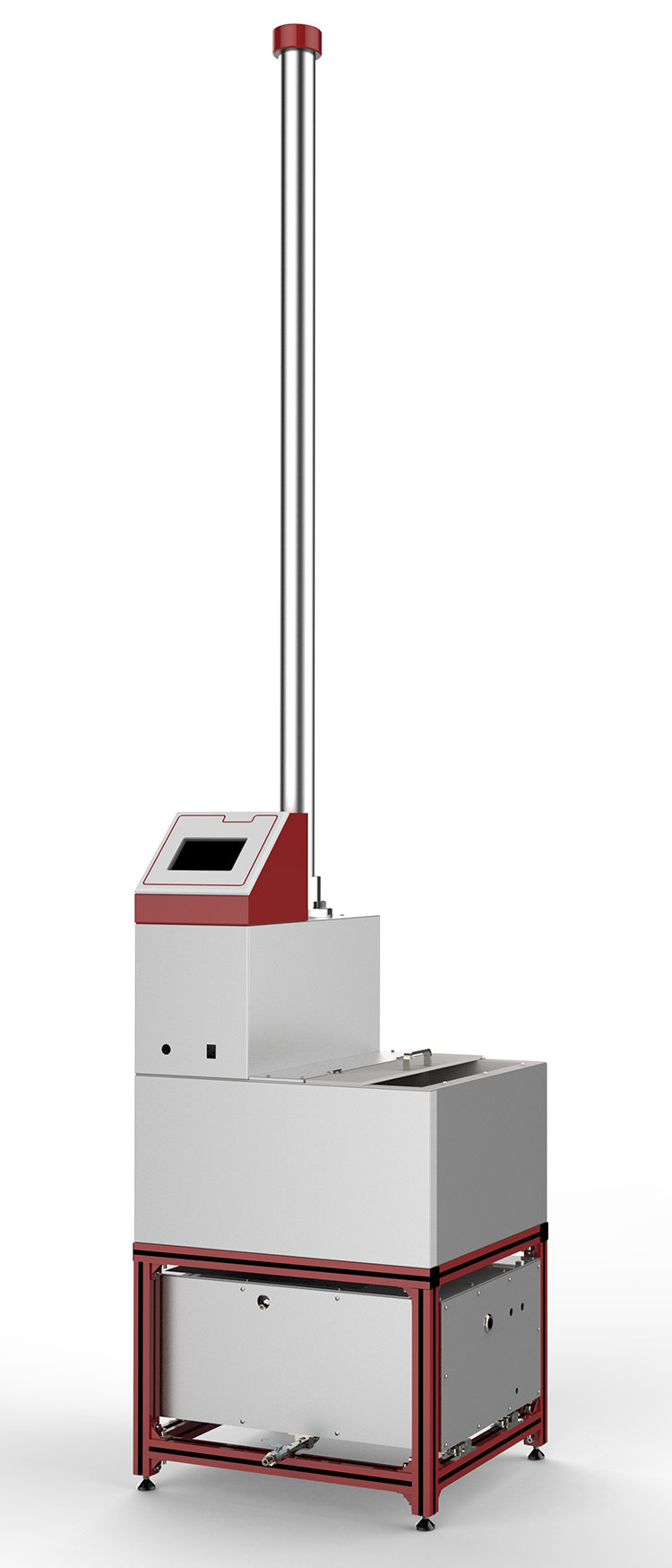
5.1 AATCC Rain Tester (see Figs. 1 and 2 and 11.3).
5.2 White AATCC Textile Blotting Paper (see 11.4).
6. Test Specimens
6.1 A minimum of three specimens of 20 × 20 cm is cut from the test fabric. The fabric samples and the blotting paper should be conditioned in an atmosphere of 65 ± 2% RH and 21 ± 1?C for at least 4 h before testing.
7. Procedure
7.1 The test specimen (see 11.5),backed by a 15.2 × 15.2 cm standard paper blotter weighed to the nearest 0.1 g is clamped in the specimen holder and the assembly is mounted in a vertical rigid support frame. The specimen assembly is positioned into the central portion of the spray at a distance of 30.5 cm from the face of the spray nozzle (see 11.6). A horizontal water spray at 27 ± 1°C (see 11.2) is directed against the specimen and is allowed to continue for a period of 5 min.
At the end of the spray period the blotter is carefully removed and quickly reweighed to the nearest 0.1 g.
8. Evaluation
8.1 Water penetration as indicated by the increase in mass of the blotting paper during the 5 min test period is calculated, and the average for the three test specimens is reported. Individual determinations or average values of over 5.0 g may be simply reported to 5 + g or > 5 g.
8.2 In order to obtain a complete overall picture of the penetration resistance of a fabric or fabric combination the average penetration with different pressure heads on the nozzle should be obtained. The pressure head should be varied by 300 mm increments in order to determine (a) the maximum head at which no penetration occurs, (b) the change in penetration with increasing head and (c) the minimum head required to cause ìbreakdown? or the penetration of more than 5 g of water. At each pressure head a minimum of three specimens should be tested in order to obtain the average penetration for that head.
9. Report
9.1 Report the individual determinations.
For values of over 5.0 g simply report as 5 + g or > 5 g.
10. Precision and Bias
10.1 Precision. Precision for this testmethod has not been established. A study,initiated in 1998, is underway to analyze the data to establish precision for this method. Until a precision statement is generated for this test method, use standard statistical techniques in making any comparisons of test results for either within-laboratory or between-laboratory averages.
10.2 Bias. The bias derived by this procedure can be defined only in terms of a test method. There is no independent, referee test method by which bias may be determined. This test method has no known bias.
11. Notes
11.1 The intensities are produced and controlled by means of a column of water which may be adjusted to 0.6, 0.9, 1.2, 1.5, 1.8, 2.1 and 2.4 m above the nozzle. This is done by means of a glass pressure column to which a nozzle is connected. The adjustment is made by a simple setting of a valve at the lower end of the drain or overflow pipe which extends up through the center of the glass column. A filtering device between the pressure gauge and the glass column may be used to prevent clogging of the nozzle openings. It may be eliminated in localities where the water supply is relatively free from iron rust or other suspended matter. A pressure gauge on the supply line also is an accessory which usually can be eliminated in the interest of economy.
11.2 The temperature of the supply water may be measured by means of a thermometer,but recent work has shown that it is more conveniently and accurately measured with a thermometer suspended in the glass pressure column or immersed in a beaker placed to catch water from the overflow.